Contents
Diffraction of Light
“The phenomenon of bending of light wave at the corners of an obstacle or an aperture (narrow opening) in the path of the light is known as diffraction.”
Due to this bending the light enters into the regions of geometrical shadow of the obstacle or that of the aperture.
“Diffraction occurs due to the mutual interference of secondary wavelets starting from different points of the part of wave-front which is not blocked by the obstacle”
The phenomena of diffraction can be observed in any wave provided the width of the edge of the obstruction is of the order of the wavelength of the wave.
There are two types of diffraction pattern
Fresnel’s Diffraction
It is observed when the light source and the screen are at finite distance from the obstacle or the slit and no lenses are used. i.e., in this case the incident beam that interact with the obstacle or the diffracted waves which interfere to produce diffraction pattern, have spherical or cylindrical wave-front.
Fraunhofer’s Diffraction
It is a type of diffraction patterns that observed when incident beam that interact with the obstacle or the diffracted wave which interfere to produce diffraction pattern, have plane wave front. This can be achieved by placing source and the screen far away from the slit. This condition is usually achieved by using convex lenses in front and behind the slit so that the source and the screen are at the focal planes of the lenses.
Diffraction (Introduction)-Video [in Hindi+English]
Diffraction of light by a Single Slit
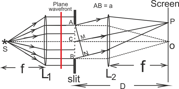
The figure shows the experimental arrangement of Fraunhofer diffraction. AB is the narrow slit of width ‘a’. The light beam originating from the monochromatic source ’S’ is made plane parallel incident beam by using convex lens L1. When the light beam emerging from the slit is passed through another convex lens L2, a complete diffraction pattern is formed on the screen placed on the focal plane of the lens.

The diffraction pattern on screen consists of an intetence central bright band (central maxima) at the centre of the screen. On either side of it there occur a number dark and bright bands, called secondary minima and maxima. The itensity (brihtness) of secondary maxima go on decreasing with increase in order of fringe.
According to Huygen’s principle every point of the wavefront ACB act as secondary source, from secondary wavelets originte and reach at every point on the screen. The diffraction pattern is the cause of interference beteween all these secondary wavelets.
Explanation of Diffraction -Video [in Hindi+English]
Explanation of Central Maxima
Every secondary wavelet that start from the secondary sources on wavefront ACB and move undeflected, reach the screen at point O. As all these wavelets cover equal optical path-length, every pair of wavelet interfere constructively. So, an intence bright band is formed.
Explanation of First order Minima
Let the point P receives all those secondary wavelets which travel making angle θ to the direction of incident beam.
The path difference between the secondary waves reaching point P from secondary sources A and B is AN = AB sinθ = a sinθ ………………….[1]
If this path difference is λ ( λ is wavelength of light), then P will be the position of first secondary minima.
If we imagine the slit AB to be divided into two equal halves AC and CB (as shown in fig), then for every point in the upper half AC, there is a corresponding point in the lower half CB, for which the path difference is CM= AC sinθ = (a/2) sinθ =λ/2.
So, any pair of wavelet one originating from a secondary source AB and another from CB interfere destructively (because path difference is λ/2) and we get a minima at point P.
So condition for first order secondary minima is
a sinθ1 = ± λ ………………………[2]
Similarly condition for n th order secondary minima is
a sinθn = ± n λ ………………………[3]
where n = 1, 2, 3, ……..
Explanation of First order Maxima
Let for another point P’ on screen the angle θ’ is such that
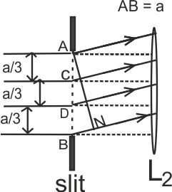
AN = AB sinθ’ = a sinθ’ = 3λ/2 …….[4]

In this case let us divide the width of slit into three equal parts, AC, CD and DB, as shown in fig. The path difference between the wave lets originating from the corresponding secondary sources of part AC and CD (having relative separation a/3) will again be λ/2. These wavelets, interfere destructively and thereby cancel the effect of one another.
The wavelets that originate from the secondary sources present in the part DB, interfere constructively (as all of them are in same phase). This generates the first secondary maxima.
Thus condition for first order maxima is a sinθ1’ = ± 3λ/2 ……………[5]
Similarly, in general, for n th order maxima a sinθn’ = ± (2n+1) λ/2 ……..[6]
where n = 1, 2, 3, ……..
FORMULAE FOR NUMERICAL CALCULATIONS
Numerical Problems on Diffraction -Video [in Hindi+English]
Fresnel’s Distance and Validity of Ray Optics Video [in Hindi+English]
Difference between Interference and Diffraction
Richard Feynman* has said in his famous Feynman Lectures on Physics:
No one has ever been able to define the difference between interference and diffraction satisfactorily. It is just a question of usage, and there is no specific, important physical difference between them. The best we can do is, roughly speaking, is to say that when there are only a few sources, say two interfering sources, then the result is usually called interference, but if there is a large number of them, it seems that the word diffraction is more often used.
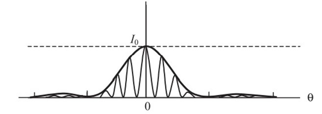
In the double-slit experiment, we must note that the pattern on the screen is actually a superposition of single-slit diffraction from each slit or hole, and the double-slit interference pattern. This is shown in Fig. below. It shows a broader diffraction peak in which there appear several fringes of smaller width due to double-slit interference. The number of interference fringes occurring in the broad diffraction peak depends on the ratio d/a, that is the ratio of the distance between the two slits to the width of a slit. In the limit of ‘a’ becoming very small, the diffraction pattern will become very flat and we will observe the two-slit interference pattern.
The Fig shows actual double-slit interference pattern. The envelope shows the single slit diffraction.

Difference between Diffraction and interference Pattern on Screen
- Interference is due to superposition of two distinct waves coming from two coherent sources. The diffraction pattern is a superposition of a continuous family of waves originating from each point on a single slit [i.e. superposition of a large number of secondary wavelets originating from different parts of the same wavefront].
- In interference pattern all bright fringes are of same intensity, where as in diffraction pattern the intensity of bright fringes go on decreasing with increase in the order of the fringes.
- In interference pattern the intensity of the dark bands is usually zero, but in diffraction pattern the intensity of dark band is never zero.
- In interference pattern all fringes are usually of same width, where as in diffraction pattern the width of the fringes are always unequal.
Resolving Power of an Optical Instrument
The power or the ability of an optical instrument to produce distinctly separated images of two closely spaced objects is called resolving power.
When a light ray enters into an optical instrument through the aperture of objective lens, a diffraction pattern is produced due to the interference of the wavelets originating from the different points of the aperture. Because of diffraction, image of a single point in the object is formed in the form of bright circular patch surrounded by a concentric, dark & bright fringes.
“According to ‘Rayleigh’, two point objects can be just resolved, when the central maxima of the diffraction pattern of the first object lie at the position of first secondary minima in the diffraction pattern of the second object.” This is called the Rayleigh Criterion for resolution.
Limit of Resolution of Optical Instrument : The minimum angular separation (or distance) between two objects which can just be seen as separate by the optical instrument to produce distinctly separate image is called Limit of Resolution of the instrument.
Smaller the limit of resolution of the instrument, greater is its Resolving Power.
Human eye is also an optical instrument. Its limit of resolution is one minute of arc. So, if two distinct objects subtend an angle on eye more than or equal to the its limit of resolution (one minute of arc), the objects can be seen separate by the eye.
